


10 Errores Comunes en el Cuadro Eléctrico de Bricolaje (y Cómo Solucionarlos de Forma Segura)
10 Errores Comunes en el Cuadro Eléctrico (y Cómo Solucionarlos de Forma Segura) Trabajar dentro del cuadro eléctrico de su hogar —el verdadero corazón del
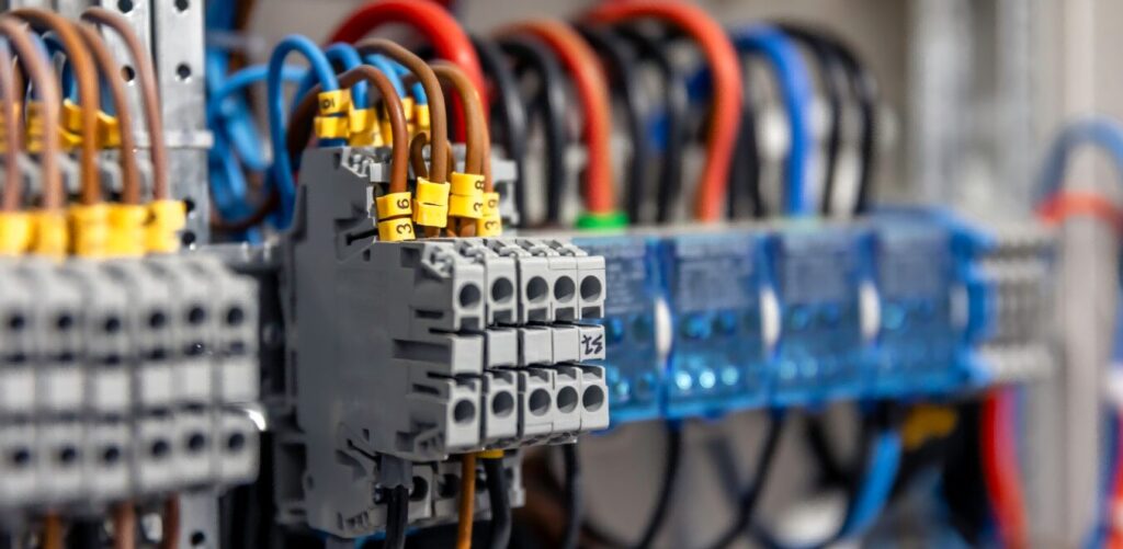
10 Errores Comunes en el Cuadro Eléctrico (y Cómo Solucionarlos de Forma Segura) Trabajar dentro del cuadro eléctrico de su hogar —el verdadero corazón del

Tuya Smart Life vs eWeLink App: ¿Qué es un Dispositivo Inteligente Tuya y Qué Plataforma de Hogar Inteligente se Adapta Mejor a Usted? Si estás

Guía Definitiva del Panel de Control Inteligente: Integración, Protocolos y Tendencias Futuras – Redefiniendo el Núcleo de su Hogar Inteligente ¿Cansado de gestionar múltiples aplicaciones
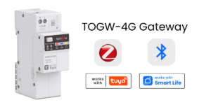
Pasarela Industrial 4G LTE con Conmutación por Ethernet | Tongou TOGW-LTNA2 ¿Es usted un integrador de sistemas o administrador de instalaciones que lucha con conectividad